

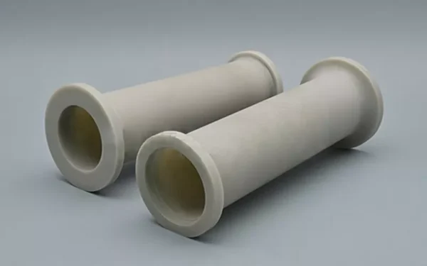


Define the sleeve by its heat path, electrical boundaries, mating surfaces and inspection evidence; material name alone is not an acceptance specification.
Key Inquiry Requirements
Map the Sleeve Into the Assembly
An aluminum nitride sleeve may separate, locate or protect a part while participating in a designed thermal path. Begin the RFQ with an assembly section showing the sleeve, heat source, heat sink, conductors, fasteners, interfaces and airflow or coolant boundaries. Explain whether the sleeve is a clearance element, a structural spacer, an insulating barrier or a combined thermal and electrical interface.
Define the bore, outside profile, length, shoulders, grooves, slots, end faces and any metallized or joined regions on the drawing. State which surfaces locate the part and which surfaces transfer heat or maintain isolation. Include insertion direction, retention method, contact pressure and service access. These details determine whether a nominal tubular form is adequate or whether end features control the design.
Thermal Requirements Need Boundary Conditions
Do not specify heat dissipation as a general product promise. Describe the heat source, contact area, heat-flow direction, adjoining materials, clamping method, interface layers, cooling conditions and allowable temperatures for the complete assembly. If thermal analysis is available, provide the model assumptions and desired outputs. A supplier can then comment on geometry, contact resistance, support and measurement needs without relying on an isolated material claim.
Thermal cycling and mismatch deserve particular attention. State ramp rates, dwell periods, start and end conditions, power cycling, mounting constraints and any repeated assembly. Review whether the sleeve sees compression, bending or local contact from fasteners. Ask for a proposed validation method that reflects the actual stack-up, because a material datasheet value may not predict installed thermal behavior.
Electrical Isolation and Interfaces
If the sleeve provides electrical insulation, define the conductors, voltage relationship, frequency or switching context, clearance, creepage path, contamination level and required test arrangement. Identify whether the ceramic must prevent direct contact, control parasitic coupling or protect a conductor from an enclosure. Keep the electrical acceptance criteria tied to the finished geometry and assembly, not only to a nominal material category.
Describe surface finish, cleanliness, coatings, metallization, bonding or brazing where they affect electrical or thermal interfaces. Residues, chips and rough transitions may matter at a contact or field-concentration point. Request an interface review covering compatible joining materials, inspection access and change control. If no electrical test is required, state the reason and define the dimensional or visual controls that support the design intent.
Fit, Finish and Quality Evidence
Specify bore size, outside diameter, length, concentricity, straightness, end-face condition and any functional fit requirement from clear datums. Explain whether the sleeve must slide, locate with an interference condition, accept a conductor or maintain a controlled gap. Surface finish should be assigned to working interfaces rather than copied across every surface. Ask the supplier to flag tolerances that may be difficult to verify after firing or finishing.
Inspection planning should cover dimensions, cracks, chips, edge damage, surface condition, cleanliness and any required thermal or electrical validation. Define sampling, measurement tools, test fixtures and reporting units before approval. For a high-consequence assembly, request traceable records and sample identification. Packaging should protect the sleeve from edge impact and contamination during handling, storage and installation.
Build a Comparable AlN Sleeve RFQ
The RFQ package should contain the component drawing, assembly section, heat-flow description, electrical boundary conditions, mounting loads, joining concept, environmental exposure and validation expectations. Mark open design questions separately from fixed requirements. Identify the interfaces that may be optimized by the supplier, but require proposed changes to be shown against the approved geometry and system constraints.
Ask for a response that addresses forming, machining, surface preparation, joining, inspection and packaging. Request technical assumptions, test conditions and any limitations that affect comparison between proposals. Do not request unsupported guarantees. Instead, define the evidence needed for design review, sample approval and production acceptance, with revision control for drawings, material designations and inspection documents.
Questions Before You Inquire
What makes an aluminum nitride sleeve specification useful?
It links the sleeve geometry to the thermal path, electrical boundaries, mounting method and mating components. Include heat-source and heat-sink interfaces, bore and outside features, contact conditions, insulation requirements, environmental exposure and inspection criteria. Without assembly context, material selection cannot be evaluated reliably.
Should thermal conductivity be the only thermal requirement?
No. Installed performance also depends on contact area, interface layers, clamping, adjoining materials, cooling conditions and thermal cycling. Describe the complete boundary conditions and request a test or analysis method that represents the assembly. Keep any numerical acceptance value tied to an agreed measurement setup.
How should electrical insulation be inspected?
Define the voltage relationship, test configuration, contamination state, contact points and acceptance method. Also inspect geometry, surface condition, cracks, chips and cleanliness because these can affect the assembled insulation path. The required evidence should describe the finished sleeve and its relevant interfaces, not only a generic material certificate.
Can the sleeve include joining or metallized regions?
It may, depending on the assembly concept and the selected process, but the drawing should identify every treated region and its purpose. Specify allowable coverage, surface condition, fit impact and inspection method. Review joining materials, thermal mismatch, electrical behavior and cleaning requirements before making those features part of acceptance.
Send a Clear Component Brief
Share your drawing, quantity and application with Porcecore. Mark the requirements that are fixed and the questions that remain open.



Reviews
There are no reviews yet.