

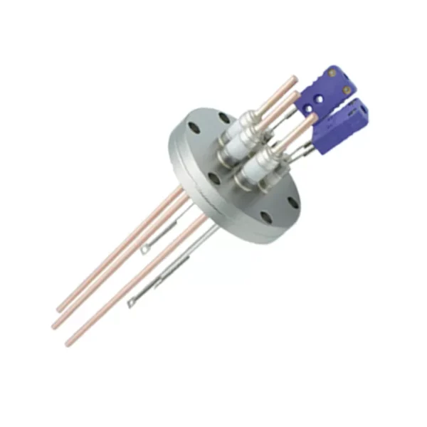

Feedthrough selection depends on the complete boundary assembly, not only the thermocouple count. Supply the mating flange or port information, conductor details, vacuum conditions and temperature program so the proposed configuration can be reviewed properly.
Key Inquiry Requirements
Define the boundary and measurement role
A thermocouple feedthrough provides a controlled path for sensor conductors across a wall, chamber or enclosure while maintaining the required boundary function. Begin the RFQ with the assembly’s purpose: temperature measurement location, chamber or vessel interface, sensor type, conductor arrangement and consequences of leakage or electrical disturbance. Explain whether the feedthrough is removable, permanent, serviceable or part of a larger instrument panel.
Identify the physical boundary that the feedthrough must cross and the direction of installation. Provide the mating port, flange, threaded feature or custom interface, including orientation references and available clearance. The drawing should distinguish the ceramic body, conductors, seals, terminals and hardware. If any of these are supplied separately, state the responsibility split so quotations do not hide incompatible assumptions.
Conductor layout and interface geometry
Thermocouple feedthroughs should be defined by conductor count, pair arrangement, polarity marking, terminal style and the sensor-side connection method. Show center spacing, pin or wire geometry, exposed length, keying and clearance requirements where they affect assembly. If multiple thermocouple circuits share one body, explain whether each circuit must remain individually identified, isolated or replaceable.
The vacuum-side and ambient-side interfaces may require different handling, connectors or protective hardware. Include mating connector information, cable routing, strain-relief needs and allowable bend or service space. State whether the feedthrough is mounted through a standard envelope or a custom port. Ask suppliers to identify any design changes needed for manufacturability while preserving the controlled connection and installation envelope.
Vacuum, bake-out and thermal definition
The source topic indicates vacuum use and a bakeable configuration, but the buyer must define the actual vacuum regime and thermal program. State target pressure or leakage requirements if known, pump-down conditions, bake-out sequence, dwell time, ramp expectations and temperature measurement locations. Include atmosphere, outgassing concerns and whether the feedthrough sees repeated cycles or one controlled process.
Do not convert a stated application temperature into an assumed universal rating. Ask the supplier to review the proposed ceramic, conductor, sealing materials and terminal arrangement against the complete cycle. Explain acceptable changes in insulation, leakage, signal stability or mechanical fit during exposure. Any quoted limit should be tied to a documented configuration and stated test or qualification basis.
Verification and quality evidence
Verification should reflect both boundary integrity and electrical function. Define the required checks for dimensional conformity, conductor continuity, insulation behavior, terminal identification, visual condition and sealing or leakage performance. State the test environment and connection method where results depend on fixtures. This prevents a generic certificate from being mistaken for evidence that the feedthrough suits the actual chamber or port.
Request an inspection record mapped to the drawing and application requirements. If the assembly includes ceramic-to-metal joints, seals or multiple materials, ask for the supplier’s proposed inspection scope and any limitations. Packaging must protect terminals, sealing surfaces and ceramic features from impact or contamination. Agree how nonconformities, substitutions and repairable damage will be reported before production.
Prepare a comparison-ready RFQ
Include the controlled feedthrough drawing, mating port or flange drawing, thermocouple and cable information, vacuum and bake-out program, installation orientation, quantity basis and documentation needs. Add a system sketch showing the chamber side, ambient side, connector access and nearby heat sources. Mark all interfaces where the supplier must preserve interchangeability or orientation.
Compare proposals by boundary-interface understanding, conductor layout, material transparency, thermal and vacuum assumptions, verification plan and listed exclusions. Ask suppliers to distinguish the feedthrough body from connectors, cables, seals, hardware and testing. Where the design is not fully frozen, request a question log and an engineering-review option rather than allowing silent substitutions in the quoted assembly.
Questions Before You Inquire
What must be included in a thermocouple feedthrough drawing?
Show the port or flange interface, ceramic body, conductor count and arrangement, polarity or circuit identification, terminal styles, center spacing, exposed lengths, orientation and clearance. Include mating connector information and distinguish supplied hardware, seals, cables and conductors. A section view is valuable where the boundary or internal layout is important.
How should vacuum and bake-out requirements be stated?
Describe the vacuum regime, leakage expectation, atmosphere, pump-down conditions, bake-out sequence, dwell time, ramp and repetition. Identify temperature locations and outgassing concerns. Avoid relying on a broad bakeable label; request the supplier’s review of the complete ceramic, conductor, sealing and terminal configuration against the actual cycle.
Are thermocouple feedthroughs interchangeable by conductor count alone?
No. Interchangeability also depends on port geometry, mounting face, orientation, conductor spacing, terminal style, polarity identification, clearances and sealing arrangement. Provide the mating assembly drawing and installation constraints. Ask suppliers to mark deviations clearly, especially when proposing a different connector, seal or body envelope.
What quality records should accompany the quotation or shipment?
Request drawing-mapped dimensional inspection, conductor continuity and identification checks, insulation-related verification where applicable, visual examination and agreed sealing or leakage evidence. Define test fixtures and conditions. If ceramic-to-metal joints or seals are present, ask for the proposed inspection scope and for substitutions or nonconformities to be reported.
Send a Clear Component Brief
Share your drawing, quantity and application with Porcecore. Mark the requirements that are fixed and the questions that remain open.


Reviews
There are no reviews yet.