

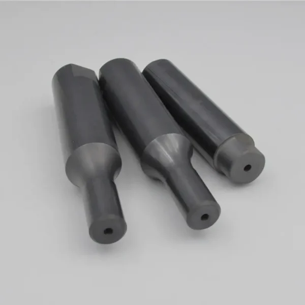

Porcecore can assess a shaped silicon carbide shaft from a controlled drawing, mating assembly or verified sample. The inquiry should explain how the profile transmits motion or locates parts, which surfaces are functional and how the shaft will be inspected, supported and protected during installation.
Key Inquiry Requirements
Define the shaft’s mechanical role
A shaped silicon carbide shaft is not simply a round rod with an unusual outline. Its profile may provide drive engagement, anti-rotation, indexing, alignment, wear separation or a controlled path through a seal or guide. Begin the RFQ by describing the shaft’s role, motion and neighbouring components. State whether it rotates, reciprocates, remains stationary or is assembled only for positioning.
The assembly drawing should show how torque, thrust, radial support and restraint are transferred. Identify splines, flats, lobes, slots, eccentric sections, shoulders or other non-round features, and explain which are functional. If the shaft runs through a bearing, guide, seal or abrasive zone, include the mating material and contact arrangement so the profile can be reviewed as a working interface.
Profile accuracy and datum strategy
A shaped shaft requires a drawing that controls the profile from a repeatable datum. Define the basic section, angular orientation, feature phase, transitions, end geometry and overall length. Show where the profile starts and ends, including any lead-in, chamfer, radius or relief. If the shape varies along the axis, provide sections at relevant stations and identify the interpolation or transition requirement.
Call out runout, straightness, concentricity or coaxial relationships only where they affect the assembly, and connect them to functional datums. The buyer should distinguish between a profile envelope and a tight mating fit. This helps the supplier select an appropriate forming and finishing route while preventing a drawing from demanding inaccessible measurements that do not improve the application.
Interface, wear and chemical exposure
Silicon carbide is often considered for ceramic shaft applications where wear, hardness or chemical resistance may be important, but suitability depends on the contact mode and environment. Describe sliding speed or cycle type qualitatively, contact pressure, lubrication or dry running, abrasive particles and the consequence of surface damage. Include whether the shaft must operate against metal, polymer, ceramic or a coated counterface.
Chemical and cleaning exposure should be described in practical terms. Identify process liquids, vapours, deposits, wash cycles and any seal materials that may contact the shaft. If the profile enters a narrow guide, explain how contamination will be cleared. These details help determine whether surface finish, edge design, coating compatibility or prototype testing should be included in the RFQ response.
Assembly and inspection planning
Installation can be a major risk for a profiled ceramic shaft. Explain whether the shaft is press-fitted, bonded, clamped, retained by a shoulder or inserted with clearance. Show insertion direction, assembly force limits if known, support points and any alignment tooling. Do not assume that a metal shaft installation method transfers directly to a brittle ceramic component without review.
Inspection should cover the functional profile, end features, straightness, runout and surface condition at contact zones. Ask for a proposed measurement method that can access the complete shaped section and identify how orientation will be established. On receipt, protect the shaft from point impacts and verify that the profile enters the mating component without forcing, scraping or twisting.
Build a useful shaft RFQ
Send the latest profile drawing, mating-part details, movement description and service environment. Include the assembly position, support arrangement, required surface zones and any known failure mode such as galling, wear, misalignment or breakage. If the geometry was reverse-engineered from an existing part, identify measured dimensions versus assumptions and request a design review before quotation is treated as final.
Ask suppliers to state their proposed silicon carbide material route, forming or machining approach, inspection plan and packaging controls. Request comments on profile transitions, achievable measurement access and assembly risks. If development pieces are needed, define the success criteria for a fit trial or endurance evaluation without turning the inquiry into a guaranteed life claim.
Questions Before You Inquire
What should a shaped shaft drawing include?
Include the complete axial profile, section geometry, orientation or phase, end treatments, shoulders, transitions and functional datums. Add the mating assembly and identify surfaces used for drive, guidance, sealing or location. If the profile changes along the length, provide multiple sections or a clear transition definition.
Does the shaft need to rotate for these requirements to matter?
No. The same issues apply to stationary locating shafts, reciprocating guides and indexing components. Any shaped shaft can have critical profile, alignment, edge and contact requirements. The RFQ should describe the actual motion or restraint condition so the supplier can assess fit, wear and inspection priorities appropriately.
How should a ceramic shaft be fitted into a metal assembly?
Define the support, clearance, retention and thermal conditions before selecting a fit. Ceramic and metal parts can respond differently to temperature, load and impact, so an assumed press fit may be unsuitable. Provide the insertion method and contact geometry, then request a review of assembly stresses and edge protection.
Which inspection results are most useful for a profiled shaft?
Results should focus on the profile at functional stations, orientation, straightness, runout, end features and contact-surface condition. The report should identify datums and measurement methods, not only list nominal values. A fit check with the mating part may also be valuable when profile interaction is more important than isolated dimensions.
Send a Clear Component Brief
Share your drawing, quantity and application with Porcecore. Mark the requirements that are fixed and the questions that remain open.



Reviews
There are no reviews yet.