
Surface Roughness Inspection for Ceramic Part Fit
Define surface roughness inspection requirements for mating surfaces, friction behavior, and assembly fit before requesting a ceramic component quotation.
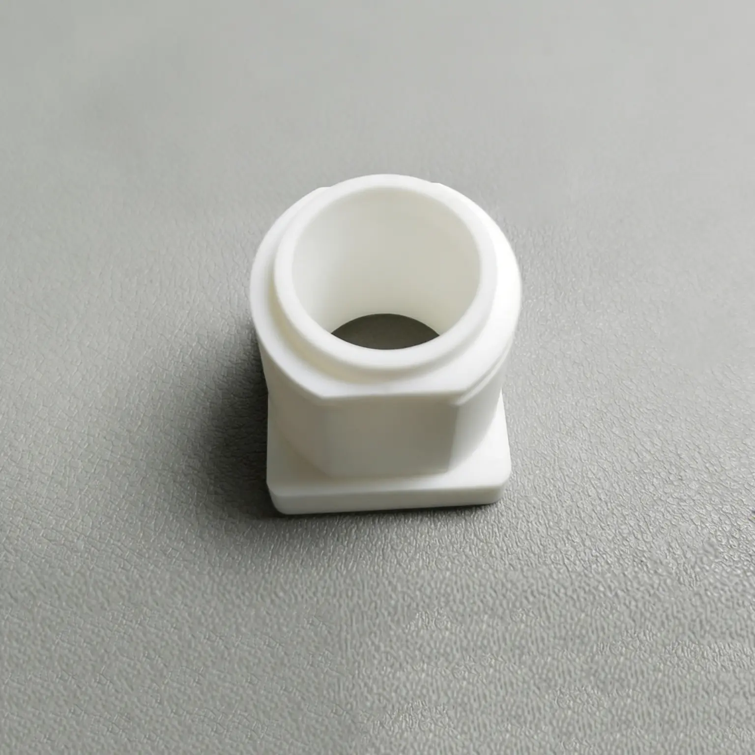
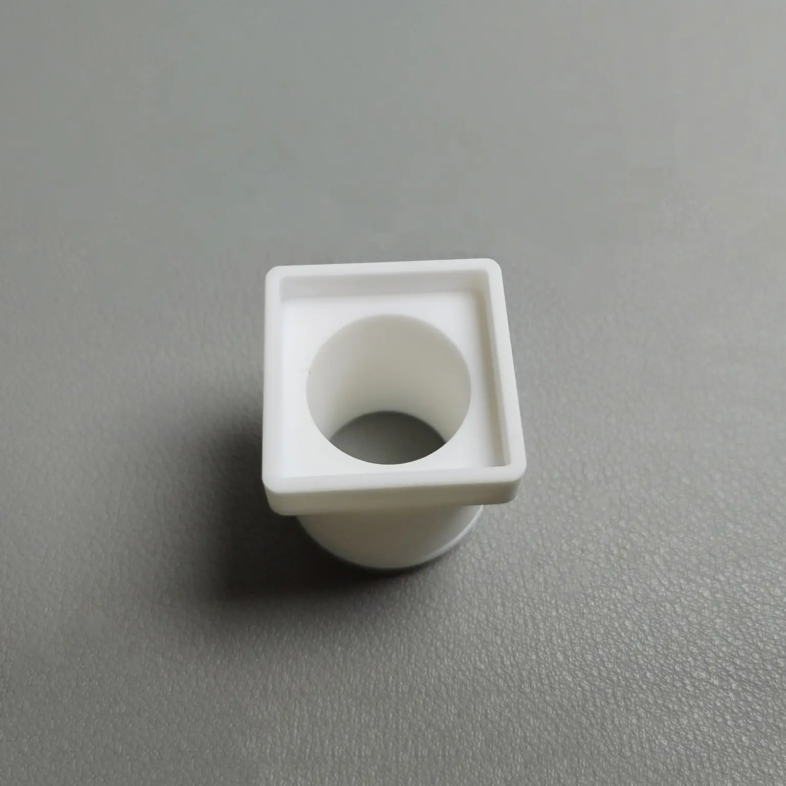
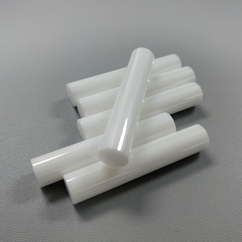
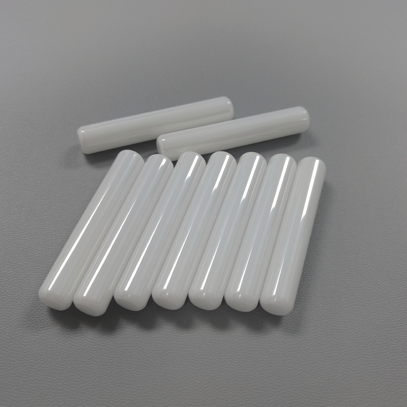
Ceramic Component Reference Gallery for Surface-Roughness Requirements
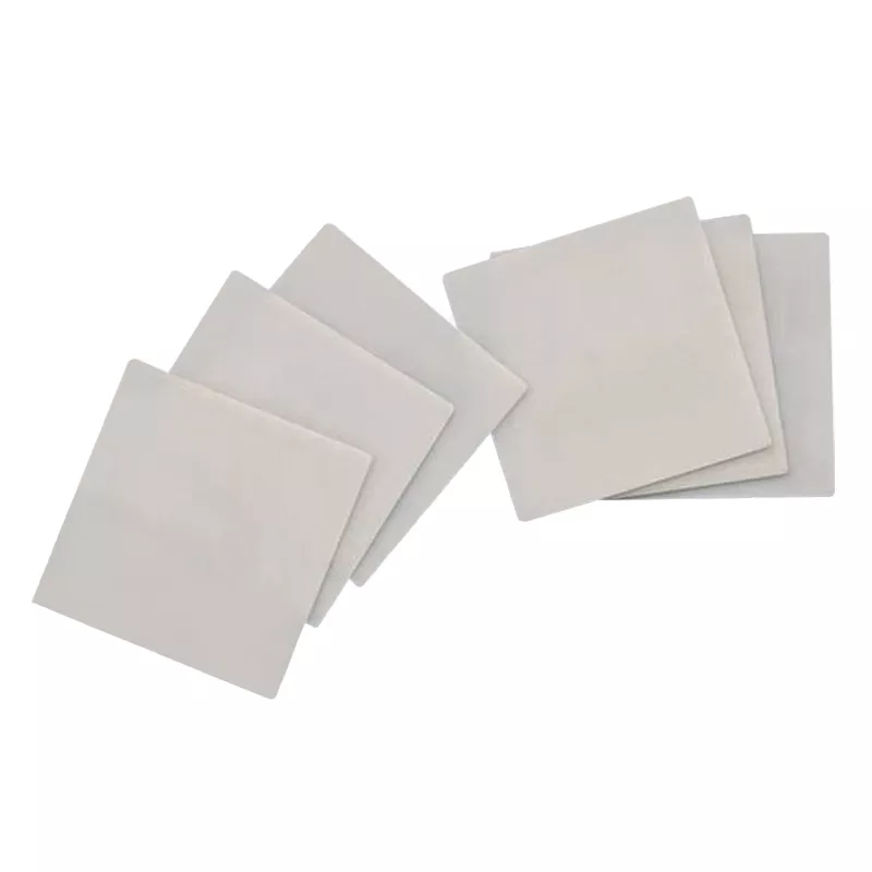
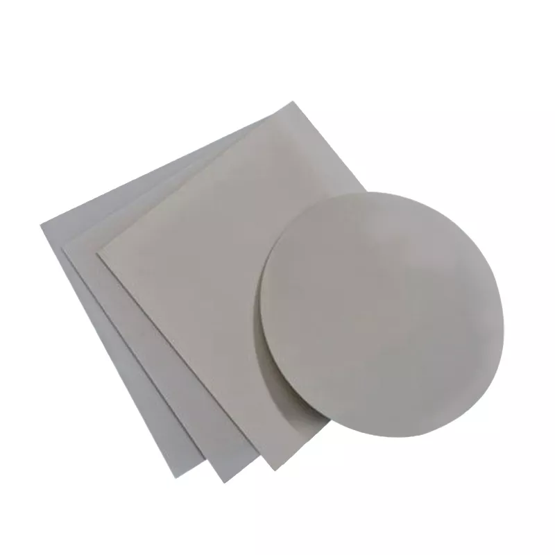
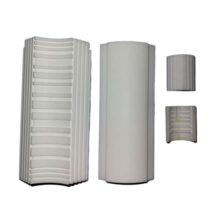

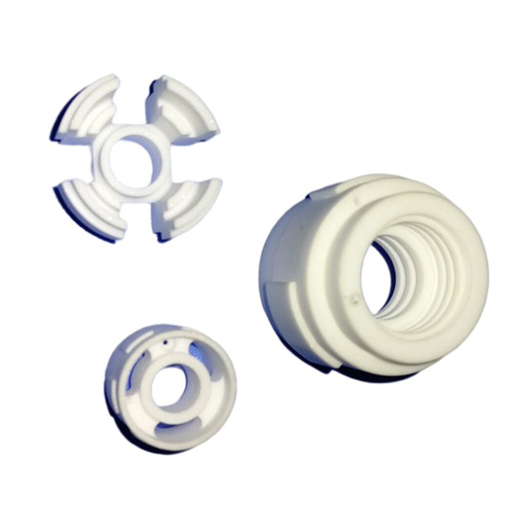



What Surface Roughness Inspection Helps You Define
Clarify the surfaces, parameters, evidence, and acceptance expectations that give a ceramic component inquiry a practical basis for review.
Drawing and Revision Control
Provide the current drawing revision and identify surface-finish callouts so the quotation discussion reflects the component definition currently intended for production.
Specified Roughness Parameters
State the required parameter, such as Ra or Rz where applicable, along with any limits or reference standard needed to interpret the surface requirement.
Measurement Direction and Area
Identify the measurement direction, evaluation area, and locations that matter, especially where ceramic surface texture may vary across a functional geometry.
Functional Mating Surfaces
Mark surfaces involved in sealing, sliding, locating, bonding, or assembly so roughness expectations can be considered alongside the component’s working relationship.
Inspection Evidence Needed
Describe the inspection records, reports, or other documentation expected for approval, allowing surface roughness inspection evidence to be discussed before commitment.
Project Acceptance Criteria
Clarify grade, geometry, service conditions, and project-specific acceptance criteria so essential ceramic requirements are distinguished from preferences during the inquiry.
Related Ceramic Components and Resources
Compare material families, component forms, applications, and inspection considerations before defining a drawing-led quotation inquiry.
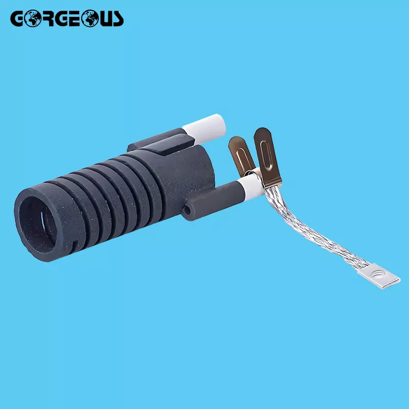
Ceramic Manufacturing Capabilities
Review ceramic manufacturing capabilities in the context of the part requirement, including geometry, critical surfaces, tolerance needs, material selection, and inspection expectations. Use this hub to identify the details needed for a practical quotation discussion.
Discuss Your Ceramic Part
Ceramic Solutions by Industry
Explore advanced ceramics applications by industry and operating environment. Compare the demands created by heat, wear, electrical insulation, chemical exposure, or structural loading, then relate them to the component geometry and material family under consideration.
Discuss Your Ceramic Part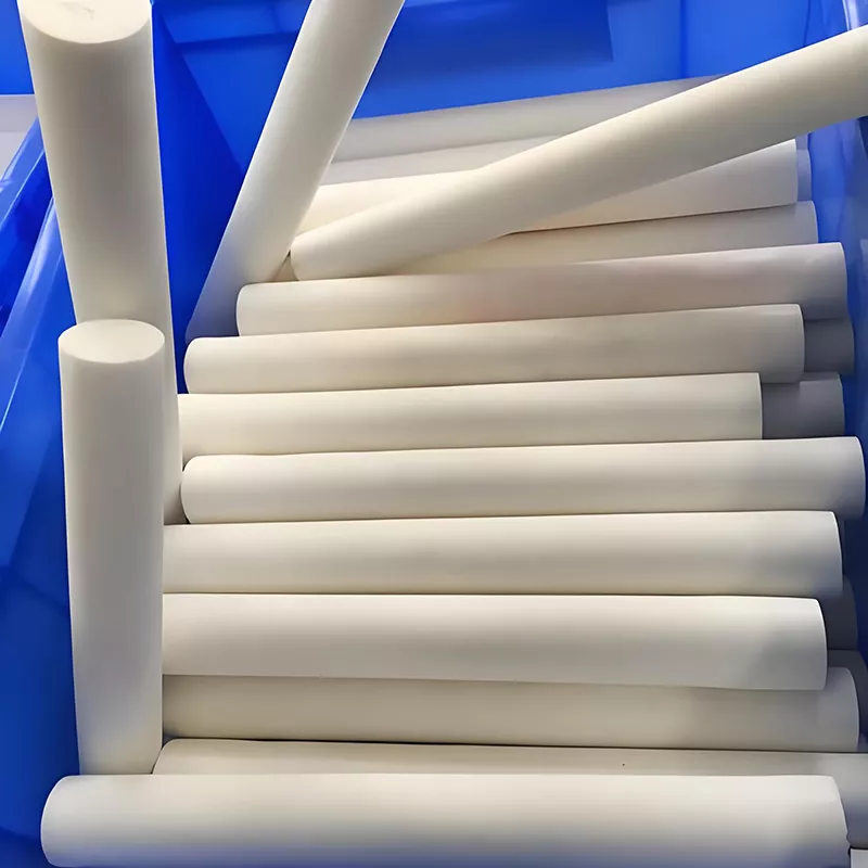
Advanced Ceramic Materials
Navigate advanced ceramic materials including alumina ceramics, zirconia ceramics, silicon carbide ceramics, silicon nitride, aluminum nitride, boron nitride, and specialty ceramics. General material information supports early comparison; the required grade and project-specific properties need confirmation for each inquiry.
Discuss Your Ceramic Part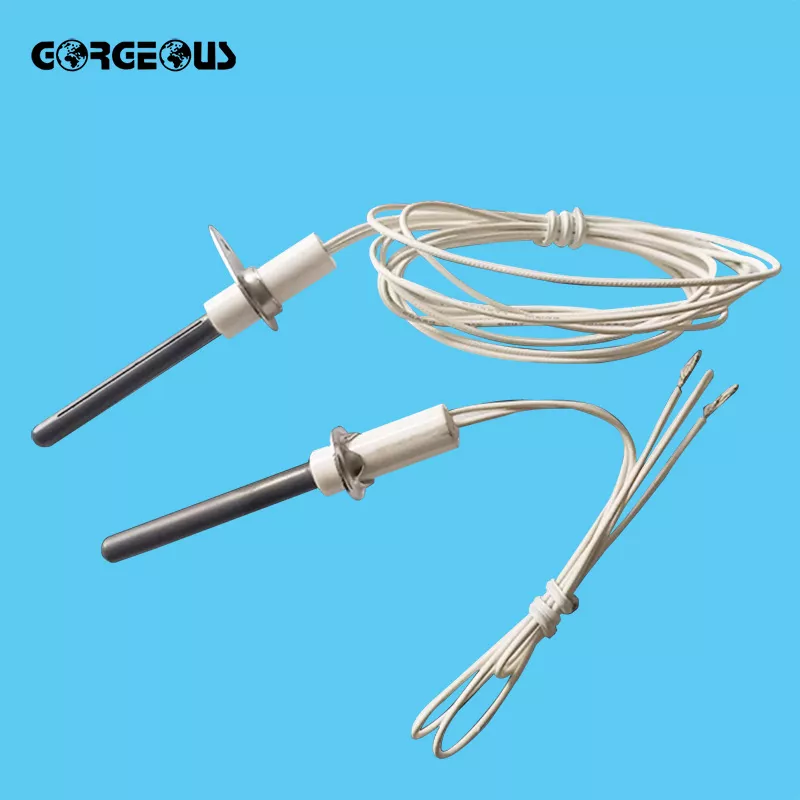
Technical Ceramic Products
Browse technical ceramic components and industrial ceramic parts by familiar form, such as tubes, rods, rings, substrates, replacement parts, and custom ceramic components. Match the product type to your drawing, assembly interfaces, service conditions, and acceptance requirements before requesting a quote.
Discuss Your Ceramic Part
Technical Ceramic Resources
Use this technical ceramics guide to clarify terminology, comparison points, and inquiry inputs. It helps procurement and engineering teams distinguish general guidance from project specifications and prepare drawings, quantities, service conditions, and documentation requirements.
Discuss Your Ceramic PartPorcecore’s Surface Roughness Inspection Approach
Porcecore is a B2B technical ceramics brand founded by Andy Yuan. We help industrial buyers, equipment builders, and project teams connect material selection with a defined component requirement, including surface roughness inspection where functional surfaces require clear acceptance expectations.
Our scope includes oxide, nitride, carbide, and specialty ceramic components. Rather than treating a material name as a complete specification, we begin with the part: its geometry, mating surfaces, operating conditions, drawing revision, and the dimensions or finish requirements that affect assembly.
Our difference is drawing-led communication before commitment. Share the current drawing, known material designation, quantity, service conditions, and inspection criteria. We use those details to identify open questions and give a quotation discussion a concrete basis. Email info@zlrsmaterials.com or message +86 130 6482 5920 on WhatsApp to begin.

Surface Roughness Inspection Requirements to Clarify
Define Ra and Rz
Specify the required roughness parameter, unit, limit, and any applicable drawing convention before quotation. Ra and Rz do not communicate the same surface information, so the requested value should match the functional requirement and be confirmed for the selected ceramic grade and process.
- Identify the required parameter and unit
- State the acceptance limit or range
- Confirm grade-specific feasibility
- Reference the current drawing revision

Locate the Measured Area
A surface-finish callout is most useful when it identifies the exact face, track, or zone to be assessed. For ceramic tubes, rings, rods, and substrates, distinguish bore, outside diameter, end face, sealing land, or another defined measurement location.
- Mark the inspection zone on the drawing
- Identify bore, OD, face, or local land
- Define any excluded edge areas
- Clarify the measurement length or area

Set the Measurement Direction
Surface texture can vary with the forming, grinding, or finishing direction. State the required measurement direction relative to the part geometry or process marks, especially where a ceramic component mates, seals, slides, or supports another part in service.
- Note direction relative to axis or feature
- Identify cross-grain requirements
- Connect direction to the mating function
- Confirm access for the specified surface

Separate Critical Faces
Not every surface needs the same finish or inspection evidence. Identify functional faces that control fit, sealing, motion, electrical contact, or assembly, then separate them from nonfunctional areas. This keeps project-specific acceptance requirements visible in the quotation discussion.
- Flag interfaces and sealing surfaces
- Separate cosmetic from functional areas
- Define required inspection records
- Confirm acceptance criteria before order

Surface Roughness Inspection vs. Visual Inspection
Use quantified surface data when ceramic mating, sealing, wear, or drawing acceptance depends on more than appearance.
← Swipe left or right to view →
Surface Roughness Inspection Workflow
Align functional surfaces, measurement expectations, and documentation needs before confirming project-specific ceramic component requirements.
Review Current Drawing
Share the current drawing revision, material designation, component geometry, quantity, service conditions, and any existing surface-finish callouts for an informed starting discussion.
Identify Functional Surfaces
Mark mating, sealing, sliding, or assembly-critical surfaces and explain their job, so surface roughness inspection focuses on the areas that influence fit and function.
Align Parameters And Criteria
Clarify the requested roughness parameter, limit, measurement direction, and acceptance criteria, distinguishing drawing requirements from preferences that still need project-specific confirmation.
Plan Measurement Approach
Discuss the proposed inspection approach, including accessible measurement locations, component condition, sampling expectations, and any report details needed for the individual ceramic part.
Review Results And Documentation
Compare available results with the agreed project criteria and confirm what documentation, drawing references, or open questions should accompany the quotation and approval discussion.
Start Your Surface Roughness Inspection Inquiry
Bring the drawing, functional surfaces, and acceptance expectations into one focused quotation discussion.
Send the Current Drawing
Share the latest drawing revision and identify the ceramic component form, key dimensions, tolerances, and any referenced material designation.
Mark Critical Surfaces
Clearly identify mating, sealing, sliding, or assembly surfaces and note the surface roughness callouts that influence fit or intended function.
Describe Service Conditions
Explain the operating environment, including load, temperature, media, wear concerns, electrical conditions, and any practical constraints affecting the component.
Confirm Quantity and Approval Needs
State the requested quantity, target timing, and documentation or inspection records needed for internal review, incoming inspection, or project approval.
Discuss Open Requirements
Email your details to Porcecore to clarify project-specific grade, geometry, surface requirements, delivery considerations, and the basis for a concrete quotation discussion.
Customer Feedback to Be Published After Approval
Placeholder for verified buyer feedback: describe how the team aligned one drawing revision, identified the mating surface, and clarified the acceptance criterion before quotation. Publish only after customer approval.
Placeholder for an approved project case: document how surface roughness inspection requirements, geometry, and required records were consolidated into one inquiry package, reducing open questions during the review process.
Placeholder for verified distributor feedback: note a specific outcome, such as clarification of two fit-critical surfaces and the agreed inspection expectation, before a ceramic replacement-part discussion moved forward.
Surface Roughness Inspection FAQ
Practical guidance for defining ceramic surface requirements before requesting a quotation.
What should a surface roughness inspection requirement include on a ceramic drawing?
Can Porcecore help interpret Ra or Rz callouts for surface roughness inspection?
Which surfaces need surface roughness inspection on a technical ceramic part?
Does measurement direction matter for surface roughness inspection?
Can roughness checks be combined with dimensional and flatness inspection?
What files should we send for a ceramic surface-finish quotation?
How should quantity and sampling needs be stated for surface roughness inspection?
What documentation and packaging details should be discussed before ordering?
Complete Buyer’s Guide to Surface Roughness Inspection
Use this decision framework to match inspection methods, parameters, and reporting needs to part function, compare qualified suppliers, and avoid costly specification, sampling, calibration, and acceptance mistakes.
1. What Is Surface Roughness Inspection?
Ra, commonly reported in micrometres, is a numerical measure of a surface’s fine production-process texture against a drawing, functional target, or process requirement. Unlike a visual check, controlled surface roughness inspection creates repeatable acceptance evidence.
Three texture scales must be separated: form is the overall shape, waviness is longer-spaced variation, and roughness is the fine, short-spaced irregularity. Filters and evaluation settings determine which scale the result represents.
One finish requirement can affect friction, sealing, wear, lubricant retention, adhesion, and appearance. Procurement should therefore tie the required parameter and inspected surface to the mating or service function, rather than treating a finish symbol as a cosmetic preference.
2. Surface Roughness Inspection: From Comparators to Digital Metrology
2D tactile comparators gave operators a fast visual-and-feel reference, but results depended heavily on lighting, access, and judgment. Stylus tracing converted a defined line into numerical profile data, improving repeatability when cutoff, evaluation length, and direction were controlled.
A portable digital profilometer can record settings and results for traceable routine checks, while CMM-mounted sensors automate access and positioning on multi-feature parts. Buyers should request the measurement path, datum strategy, calibration status, and report format—not merely an Ra value.
3D non-contact optical methods capture area data without dragging a tip across delicate surfaces and can reach complex topography where a stylus is constrained. Their capability differs because optics, lateral resolution, filtering, reflectivity, and line-of-sight affect what is captured and comparable.
3. Types of Surface Roughness Inspection
Five inspection types trade data depth against access, cycle time, and part risk. Select the method from the drawing’s functional surface, geometry, acceptance parameter, and production decision.
| Type | Principle And Fit | Output / Speed | Risk And Limitation |
|---|---|---|---|
| Stylus profilometer | Diamond tip; accessible flats, cylinders, hard ceramics | Ra, Rz, trace; moderate | Contact marks; narrow or steep features restrict access |
| Portable tester | Handheld stylus; machined, reachable production surfaces | Ra/Rz; fast | Setup-sensitive; limited trace and geometry access |
| Benchtop laboratory | Controlled stylus scan; complex fixtured parts | Profile, parameters; slower | Contact and alignment demand |
| Optical 2D/3D | Light-based scan; delicate, textured, complex surfaces | Maps, Sa; moderate | Reflectivity, transparency, slope, and cost limit use |
| Comparator | Visual/tactile reference; broad accessible surfaces | Screening; fastest | Subjective; no numerical record |
Production Or Investigation
100% production checks usually favor portable testers after a documented setup proves repeatability. Detailed investigation favors benchtop or optical profiling when trace shape, localized defects, or areal texture matters.
4. Surface Roughness Inspection for Different Materials
Material changes both the measurement signal and the risk of changing the surface. Surface roughness inspection should therefore define the finish condition, contact allowance, cleaning method, and datum support before selecting an instrument.
| Material or Finish | Inspection Preference | Primary Risk |
|---|---|---|
| Metal | Stylus or optical | Burrs, oil film |
| Engineering ceramic | Light-contact or optical | Edge chipping, brittle surface |
| Coated part | Optical first | Coating damage or thickness influence |
| Polymer or soft surface | Non-contact optical | Stylus deformation, heat |
| Sensitive surface | Non-contact optical | Marks from contact or clamping |
Ceramic Surface Conditions
Ground ceramics usually suit a light-contact trace when the drawing permits it; polished, glazed, or coated areas may favor optical measurement to avoid scratches.
Specify the actual condition—ground, polished, glazed, or coated—and keep support away from functional edges.
5. Parameters and Reporting Requirements
Ra, Rz, and Sa are not interchangeable acceptance values. Surface roughness inspection results are comparable only when the parameter, units, instrument settings, and measured location match.
| Parameter | Data Type | Specify With |
|---|---|---|
| Ra | Profile average | Cut-off, length, direction |
| Rz | Profile height | Filter, sampling location |
| Sa | Areal average | Area, resolution, processing |
Define The Parameter
Ra is an average profile-height value; Rz describes profile peak-to-valley behavior; Sa is an areal average-height value. State µm or µin and the applicable limit.
Lock Measurement Conditions
Specify cut-off, evaluation length, filter, sampling location, and traverse direction relative to machining marks. Optical Sa also needs measurement area and processing settings; method differences can change results.
Require Traceable Reports
Each report should identify part number and revision, method, calibrated equipment, settings, individual readings, acceptance criterion, pass/fail result, and exceptions. Link locations to the drawing or a marked inspection map.
6. Inspection Setup and Quality Controls
A defensible surface roughness inspection starts before the instrument touches the part. The drawing should identify the functional surface, datum, trace direction, parameter, cutoff, and acceptance rule.
Prepare And Locate Specimens
Before each run, remove loose coolant, grit, and handling residue without altering the surface. Fixture the component rigidly from defined datums; record the exact measurement locations and surface direction.
Control The Measurement System
At shift start, verify calibration status and check the instrument against a traceable reference artifact. Isolate vibration, retain approved settings, and use the same stylus or optical setup specified by the plan.
Prove Repeatability
For each lot, repeat readings at documented locations and retain raw results, setup records, and operator identification. A one-off check reports a value; a controlled plan validates agreement across operators, lots, and suppliers.
7. How to Choose a Surface Roughness Inspection Supplier
Two sample parts can reveal whether a supplier’s claimed method range, access, and reporting match the drawing. Qualify surface roughness inspection against the actual critical surfaces, not a generic capability list.
| Qualification Area | Evidence To Request | Marketing Claim To Avoid |
|---|---|---|
| Method fit | Procedure and sample report | Universal capability |
| Calibration | Current traceable certificates | Calibrated equipment |
| Drawing communication | Marked-up measurement plan | Understands specifications |
Request Objective Evidence
Request calibration certificates, method procedures, sample reports, and uncertainty statements. Confirm traceability, parameter, cutoff, evaluation length, stylus or optical setup, and report revision control.
Check Part Access
Review the current drawing with the inspector. Verify fixture approach, part-size limits, curved or internal-feature access, material experience, sampling plan, capacity, turnaround, and nonconformance escalation.
Choose Data Independence
Use in-process supplier data for routine control after correlation is established. Use an independent lab for first articles, disputes, critical acceptance, or when measurement access and impartial reporting matter.
8. Common Surface Roughness Inspection Mistakes
A single Ra value rarely creates a repeatable acceptance decision. Most disputes begin when the drawing leaves the measured feature, filtering conditions, method, or record undefined.
Define The Texture Target
Ra alone can pass a surface with unacceptable peaks, waviness, or form error. Specify the required parameter and separately control the functional condition.
A missing cut-off, evaluation length, or lay direction lets two valid instruments report unlike results. Put those settings and measurement direction on the drawing.
Match Method To Feature
A stylus may not access a narrow radius, while an optical scan can miss the intended functional track. Select a method, sampling area, and resolution suited to the geometry.
One convenient spot can falsely accept a locally damaged sealing or fit surface. Define representative locations, quantity, and exclusions before inspection.
Control Condition And Evidence
Oil, debris, handling marks, and coating condition can distort surface roughness inspection. State the required surface condition and cleaning sequence before measurement.
A calibrated instrument does not prove the selected method is suitable. Require records of part revision, settings, locations, operator, raw results, and calibration status; otherwise acceptance can be disputed.
9. Steps to Launch a Qualified Inspection Program
A controlled program starts when the functional surface is translated into an unambiguous drawing requirement. Engineering, quality, procurement, and the manufacturing partner should agree on each decision before release.
Define The Requirement
Step 1: identify the mating or functional surface, its direction, parameter, limit, cutoff, and applicable drawing revision.
Step 2: distinguish a functional acceptance limit from a preferred finish; record material, process stage, and service condition.
Qualify Measurement
Step 3: select tactile or optical measurement, locations, orientation, and sample size. Obtain calibration status, method settings, and repeatability evidence from the responsible laboratory.
Step 4: run a correlation trial on representative parts before approving the measurement-system result.
Control And Improve
Step 5: approve a report template linking results to part ID, surface location, parameter, settings, and disposition.
Step 6: set incoming or in-process checks, assign nonconformance ownership, and review trends with the manufacturing partner.
10. Surface Roughness Inspection Pricing and Lead Times
Two cost categories govern most surface roughness inspection quotes: one-time setup and per-part measurement. Method selection, difficult access, the number of specified locations, and a full trace/report package increase both labor and review time.
Three quote inputs make schedules comparable: drawing revision, required parameter and limit, and quantity. Also state the evaluation length or method if defined, surface locations, material/geometry, report format, required date, and whether the work is a first article or repeat production.
| Inspection scope | Primary cost drivers | Lead-time factors |
|---|---|---|
| One part, first article | Setup, fixturing, method review, report | Part access and approval questions |
| Small batch, multiple locations | Measurement count, complex geometry, reporting depth | Sampling plan and data review |
| Repeat production | Per-part readings, change control, periodic reporting | Stable setup; urgent requests may add scheduling constraints |
Discuss Your Surface Roughness Inspection Requirement
Email your drawing, ceramic part details, operating environment, critical surfaces, and acceptance criteria for a project-specific discussion with Porcecore.