
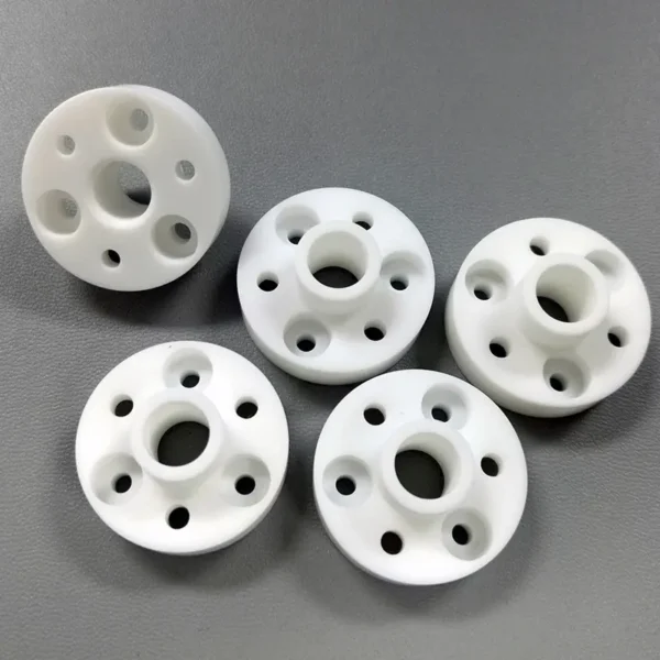
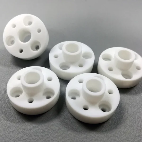
Use this page to prepare a complete inquiry for machinable ceramic flange bushings. The component form is the starting point; the final selection should follow the drawing, assembly function, material documentation, inspection plan and application constraints agreed with the supplier.
Key Inquiry Requirements
Define the flange bushing’s role in the assembly
A flange bushing can locate, space, guide, isolate or retain another component, and the drawing should make that role explicit. Show the bore, outside diameter, flange diameter, flange thickness, shoulders and any reliefs with clear datums. Include the part it supports or passes through, because an apparently straightforward bushing can have different priorities when it carries alignment, separation, sealing or axial retention duties.
Describe how the bushing is installed and loaded. Note whether it is pressed, clamped, bonded, captured, slipped into a housing or used with a fastener. Identify radial, axial and impact loads in practical terms, together with movement during service. The supplier needs to know which surfaces are functional, which edges must remain intact and whether the flange acts as a locating stop or merely provides clearance.
Use machinability as a design input, not a vague promise
A machinable ceramic designation does not remove the need to define the intended finish and feature quality. Ask the supplier to state the proposed material designation and machining route, then review how the route supports the bore, flange faces, shoulders, slots or holes shown on the drawing. Where features are especially sensitive, identify the inspection method and reference surfaces used to verify them.
Compare proposals by the complete manufacturing approach rather than by the word machinable alone. Relevant discussion may include stock form, roughing and finishing sequence, edge protection, cleaning and handling after machining. If the bushing will be assembled with a metal housing or shaft, request guidance on fit assumptions and thermal or chemical conditions, while keeping final dimensional requirements under drawing control.
Clarify fits, shoulders and mating surfaces
The bore and outer surface should be specified in relation to their mating parts, not as isolated numbers. Provide shaft, pin, housing or plate information where available, including assembly direction and any retaining method. Mark whether the flange face controls axial position, whether the bore guides motion and whether a shoulder must seat against a particular datum.
Surface condition can influence insertion, movement and contamination. State where a ground, machined or otherwise finished region is required, and explain why. Define edge breaks, corner radii and allowable chips by functional area. If the bushing works in a vacuum, electronics fixture, automated mechanism or heated assembly, include the relevant cleaning and outgassing questions in the RFQ.
Inspect the geometry that holds alignment
Inspection should cover the relationships that make the bushing useful, not only its individual dimensions. Depending on the approved drawing, this may include bore size, outside diameter, flange thickness, face parallelism, perpendicularity, concentricity, runout and shoulder location. Avoid importing metal-part tolerances without checking ceramic process capability and the actual assembly requirement.
Ask for a measurement plan that identifies datums, gauges or instruments and the condition of the part during inspection. A dimensional report can be more useful when it distinguishes critical features from reference dimensions. For small or delicate flange edges, agree how visual inspection, chip limits and handling damage will be judged. This gives the quotation a measurable acceptance framework without inventing requirements.
Prepare an RFQ for a custom bushing
Include the latest drawing, assembly section view, expected quantity range and any existing sample or failed part. Explain installation, duty cycle, motion, contact materials, process chemistry and cleaning route. Identify whether the design is replacing a metal bushing, adapting to a new fixture or solving an insulation or wear concern. These details help the supplier review the design as a component rather than a generic tube.
Ask each supplier to return a marked-up clarification list, proposed material designation, manufacturing route, inspection scope and packaging assumptions. Separate quotation options from confirmed compliance. If the supplier recommends a change to flange thickness, bore fit or edge treatment, require that change to be shown and approved before it enters the controlled design.
Questions Before You Inquire
What drawings are useful for a flange bushing quotation?
Send the part drawing together with an assembly section view showing the shaft, housing, plate, fastener or retaining feature. Include datums, critical fits, flange function and revision status. If installation has caused previous damage, add photographs or failure notes so edge and handling risks can be evaluated.
What makes a machinable ceramic bushing different from a generic ceramic sleeve?
The flange introduces axial location, seating and edge requirements in addition to bore and outside-diameter control. The RFQ should define flange relationships, shoulders, installation direction and mating parts. Machinability still needs to be tied to the proposed material, process route and required inspection evidence.
Should the bushing have a press fit?
That depends on the housing, shaft, temperature, loading and installation method. Do not assume a press fit from the component name. Provide mating dimensions and assembly conditions, then ask the supplier to review the proposed fit. Put the final requirement and any installation limits on the approved drawing.
Can a sample replace a controlled drawing?
A sample is useful for geometry review, but it may not reveal hidden datums, fit intent, material identity or acceptance criteria. Use measured sample data only as a starting point. A controlled drawing and assembly context are needed before a custom quotation can be compared reliably.
Send a Clear Component Brief
Share your drawing, quantity and application with Porcecore. Mark the requirements that are fixed and the questions that remain open.


Reviews
There are no reviews yet.