

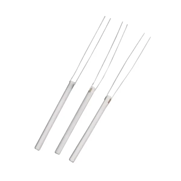

Use the RFQ to distinguish the heater’s ceramic body from the complete soldering-iron assembly. Supply a controlled drawing or model showing the ring or washer form, lead or contact features, insertion direction and mating hardware. State how resistance, insulation, power input, temperature response and repeatability will be evaluated, without assuming that a catalog description defines the required acceptance standard.
Key Inquiry Requirements
Define the heating element in the tool
Begin with the soldering iron’s mechanical and electrical architecture. Explain whether the ceramic element sits around a tip, inside a sleeve, against a support or within a layered heater assembly. Show the available envelope, insertion direction, retention method and adjacent materials. These details determine which ring, washer or custom ceramic profile can be reviewed responsibly.
Do not use the word universal as a substitute for interface information. Identify the tool family, intended assembly relationship and any replaceable subcomponents that touch the heater. If the element must fit an existing housing, provide the receiving-part drawing and controlled clearance requirements so the supplier can assess fit without guessing from a photograph or product title.
Set electrical requirements clearly
The stated 10W–40W range should be treated as a starting classification, not as a complete electrical specification. Define nominal voltage, target resistance, allowable resistance variation, connection method, polarity requirements if applicable and the intended control strategy. State whether the element is driven continuously, intermittently or through a regulated cycle.
Also identify the required insulation relationship between the resistive path, ceramic body, contacts and surrounding metalwork. Explain which values are checked at incoming inspection and which are verified during tool validation. A quotation becomes more comparable when electrical characteristics are written as controlled requirements rather than inferred from an advertised power band.
Review thermal transfer and assembly
Heating performance depends on how the ceramic element contacts the tip, sleeve, clamp or support. Show contact surfaces, fit conditions, assembly pressure and any interface material. Identify where heat should move and where electrical separation must remain. If the design uses a ring or washer as part of a stack, provide the complete stack-up rather than isolating one component from its functional context.
Describe the operating cycle in practical terms, including start-up expectations, dwell periods, switching frequency and cooling intervals where known. Avoid relying on a generic temperature claim. The supplier can better review the element when the RFQ explains the tool’s heat path, control method and the consequences of uneven contact or movement.
Inspect ceramic and connection features
Inspection should cover both the ceramic geometry and the electrical interfaces. Identify critical diameters, thicknesses, concentricity, openings, contact locations and edge conditions. State how cracks, chips, contamination, surface irregularities and damaged connection areas will be assessed. If the element is installed under pressure, identify the surfaces that must remain stable during assembly.
Request clarity on how resistance and insulation checks are performed, when they are measured and how results are recorded. If the heater is supplied as a component rather than a finished tool, define which tests belong to component acceptance and which belong to the assembled product. This separation keeps supplier comparisons technically fair.
Prepare a tool-specific RFQ
A strong RFQ includes the latest drawing, electrical targets, interface model, material description, assembly sketch and intended application. Add the 10W–40W designation only as context, then state the exact selected operating point if one has been chosen. Include documentation, sample approval, marking, cleanliness, packaging and any required change-control process.
Ask bidders to identify assumptions about power, resistance, fit, contact method and test conditions. Request proposed clarifications for dimensions that are absent or ambiguous. A drawing-led inquiry helps distinguish a heater that merely resembles the requested form from one that can be evaluated against the tool’s real mechanical and electrical requirements.
Questions Before You Inquire
Does the 10W–40W label define the required heater?
No. It identifies the product topic and a stated range, but the RFQ should define the selected voltage, resistance, power condition, duty cycle, connection arrangement and acceptance tests. The tool’s actual interface and heat path must also be supplied before a component can be compared responsibly.
What drawings are useful for a soldering-iron heater RFQ?
Provide the heater drawing or controlled model together with the receiving sleeve, tip support, contacts and retention features. An assembly section is especially useful because it shows clearances, contact surfaces and the thermal path. Photos can supplement the package but should not control dimensions or fit.
Which electrical checks should buyers specify?
Define the resistance measurement condition, allowable variation, insulation verification method and any continuity or connection checks required at incoming inspection. Also state whether component results differ from assembled-tool validation. The supplier should not be expected to infer acceptance limits from a nominal wattage range.
Why do mounting details matter for a ceramic heater?
Mounting affects contact, heat transfer, movement and mechanical stress. A ring or washer can behave differently depending on clamping, sleeve fit, support surfaces and adjacent materials. Include the stack-up, assembly sequence and retention method so the design review addresses the installed element rather than an isolated ceramic shape.
Send a Clear Component Brief
Share your drawing, quantity and application with Porcecore. Mark the requirements that are fixed and the questions that remain open.


Reviews
There are no reviews yet.