
Ceramic Feedthrough Components, Clearly Specified
Start with your drawing, operating conditions, interfaces, and acceptance criteria to discuss ceramic feedthrough components with a clearer sourcing basis.
Featured Industrial Ceramic Parts and Feedthrough Components
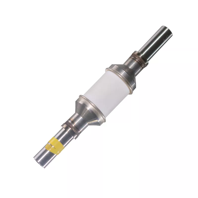
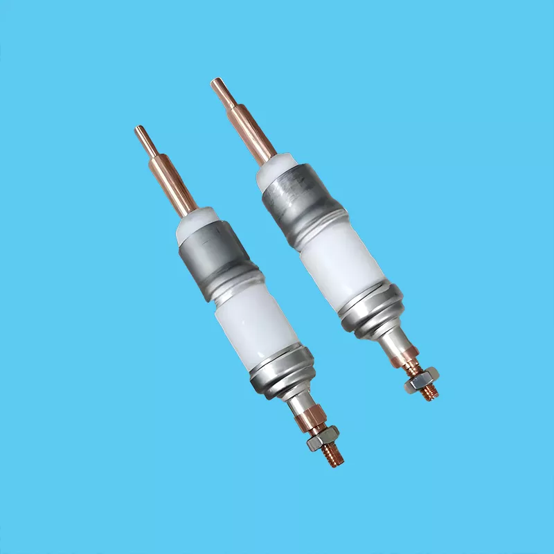
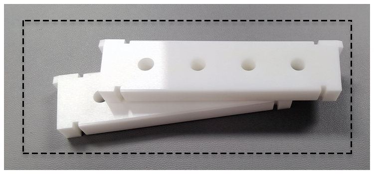
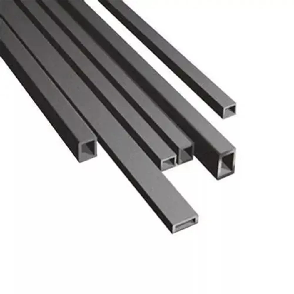
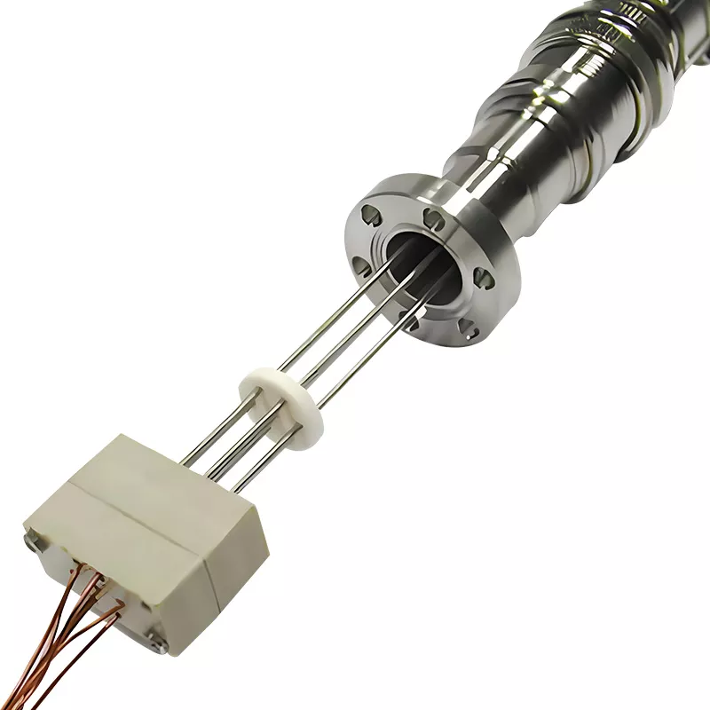


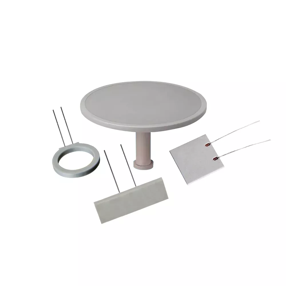


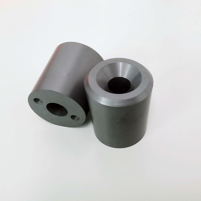

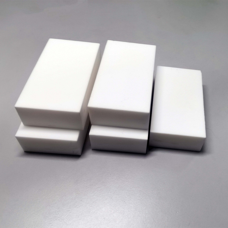
Ceramic Feedthrough Components: Catalogue and Quotation Inquiry






Ceramic Feedthrough Components: Define Requirements Before Quotation
Clarify the details that connect material selection, assembly fit, service conditions, and acceptance expectations before a project-specific sourcing discussion.
Current Drawing Revision
Share the current drawing revision and identify controlling dimensions so the quotation discussion starts from the intended configuration rather than an outdated illustration or assumption.
Material Grade Context
Name the preferred ceramic material or describe the electrical, thermal, mechanical, and environmental demands that should guide grade selection for the individual application.
Assembly-Critical Geometry
Define profiles, wall sections, conductor locations, and dimensions that govern installation, clearance, or alignment with adjoining hardware in the finished equipment.
Functional Surface Requirements
Identify mating surfaces, finish expectations, sealing interfaces, and areas where surface condition affects fit, joining, electrical isolation, or in-service function.
Operating Conditions Explained
Describe voltage, temperature, pressure or vacuum exposure, media, cycling, and other application conditions that may influence the appropriate ceramic feedthrough components discussion.
Inspection Evidence Needed
State the acceptance criteria, dimensional checks, material documentation, or inspection evidence required for approval, so expectations can be reviewed before commercial terms are confirmed.
Feedthrough Components, Materials, and Inquiry Routes
Start with a drawing, service conditions, or replacement part to define the ceramic component, material, interfaces, and acceptance requirements.
Ceramic Manufacturing Capabilities
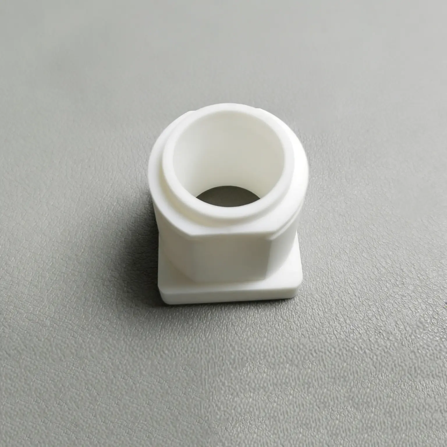
Ceramic manufacturing capabilities for feedthrough-related components begin with the part requirement: tube, insulator, ring, seal interface, or custom geometry. Share the drawing revision, critical dimensions, mating surfaces, quantity, and inspection expectations for a project-specific quotation discussion.
Discuss Your Ceramic Part
Ceramic Solutions by Industry
Explore advanced ceramics applications by operating environment and equipment role. Feedthrough projects may involve electrical isolation, vacuum boundaries, thermal exposure, chemical contact, or mechanical loading. Describe the assembly, service conditions, and performance concerns so the component requirement can be reviewed in context.
Discuss Your Ceramic Part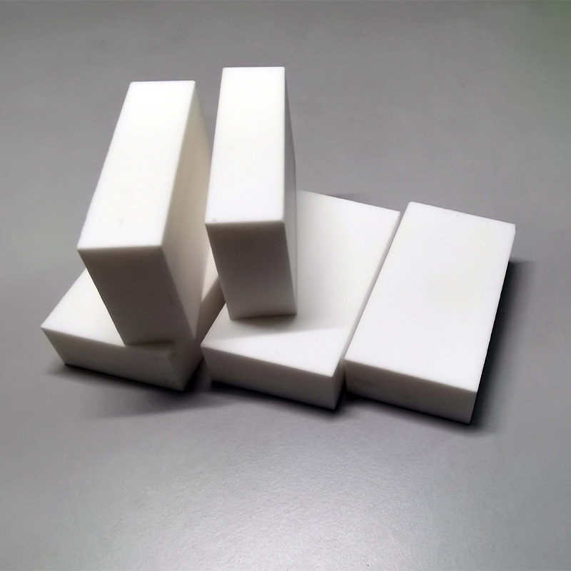
Advanced Ceramic Materials
Advanced ceramic materials including alumina, zirconia, silicon carbide, silicon nitride, aluminum nitride, boron nitride, and specialty ceramics can be considered for feedthrough components. Material selection must be confirmed with geometry, operating conditions, electrical needs, and the specific grade required for the project.
Discuss Your Ceramic Part
Technical Ceramic Products
Technical ceramic components cover familiar forms such as tubes, rods, rings, substrates, insulators, and custom ceramic components made from approved drawings. A product image or material family is a starting point for inquiry; dimensions, tolerances, grade, documentation, delivery, and commercial terms require project confirmation.
Discuss Your Ceramic Part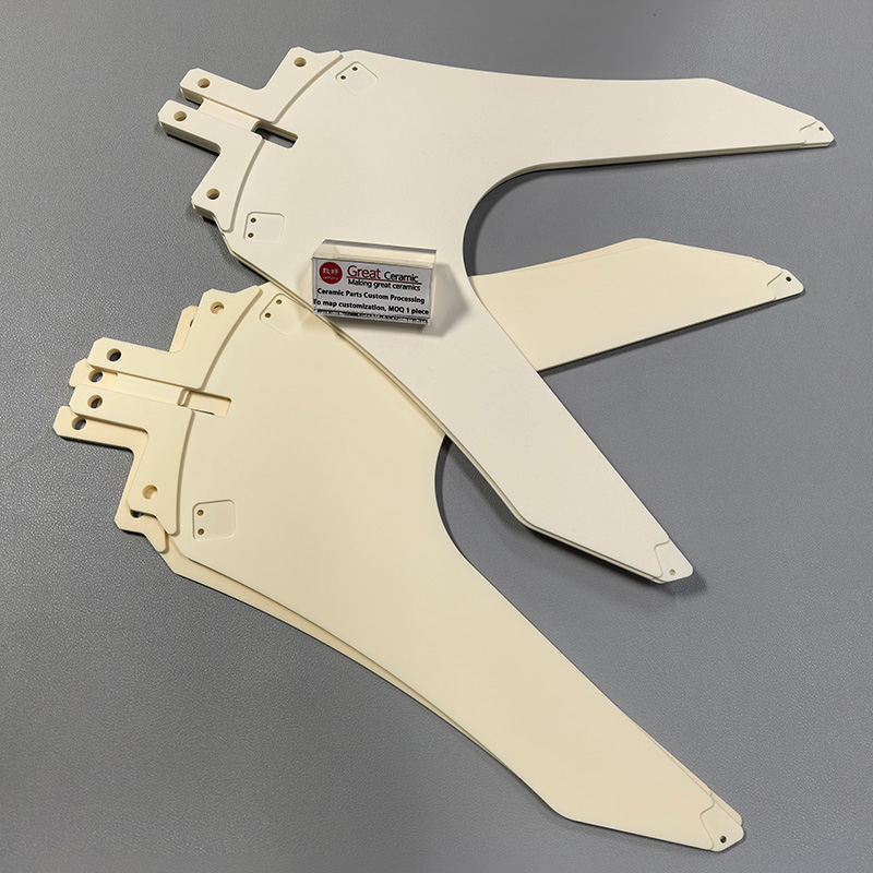
Technical Ceramic Resources
Use the technical ceramics guide as a starting point for preparing a clearer inquiry. Identify the current drawing, replacement-part reference, material designation if known, functional surfaces, service environment, quantity, and acceptance criteria. Send the details by email or WhatsApp to begin the discussion.
Discuss Your Ceramic PartCeramic Feedthrough Components: Materials to Review
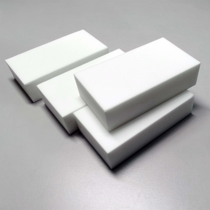
Alumina Ceramics
A widely considered insulator for ceramic feedthrough components, alumina suits many electrical isolation and structural-part discussions. Review the required grade, metallized surfaces, conductor layout, and dimensional tolerances against the drawing.
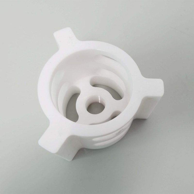
Zirconia Ceramics
Zirconia can be considered where a robust ceramic form and specific assembly interfaces shape the requirement. Discuss the intended environment, mating surfaces, geometry, and grade-specific expectations before selecting it for a feedthrough project.

Silicon Carbide Ceramics
Silicon carbide may enter the discussion for demanding thermal, wear, or chemical service conditions around associated ceramic parts. Define the component’s function, temperature exposure, interface details, and inspection requirements before material selection.

Silicon Nitride
Silicon nitride is a technical ceramic family worth reviewing when mechanical loading and operating conditions influence the part decision. Share the drawing revision, assembly loads, surface requirements, and acceptance criteria for a project-specific conversation.

Aluminum Nitride
Aluminum nitride may be relevant when thermal management and electrical insulation are both part of the design question. Confirm the required geometry, conductor arrangement, joining approach, and environmental conditions rather than relying on material name alone.
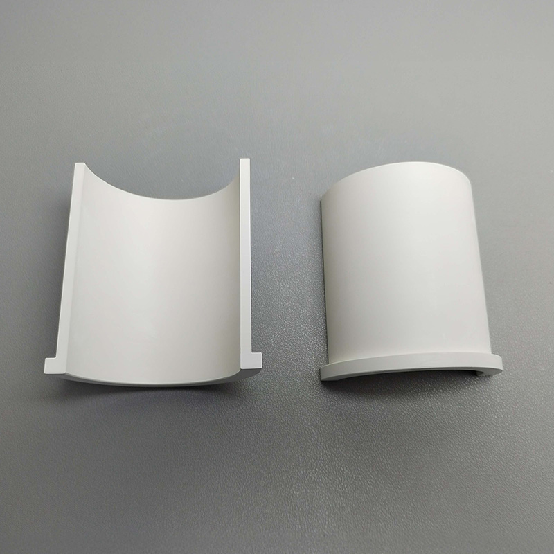
Boron Nitride
Boron nitride and other specialty ceramic families can be explored for application-specific needs. A useful inquiry identifies the service environment, component form, critical dimensions, mating surfaces, and any documentation needed for approval.
Ceramic Feedthrough Components: Production and Joining Considerations

Ceramic Forming
Forming routes are considered against the requested geometry, wall sections, pin pattern, and dimensional priorities. Share the current drawing so the part shape and practical manufacturing approach can be reviewed together.
Green Machining
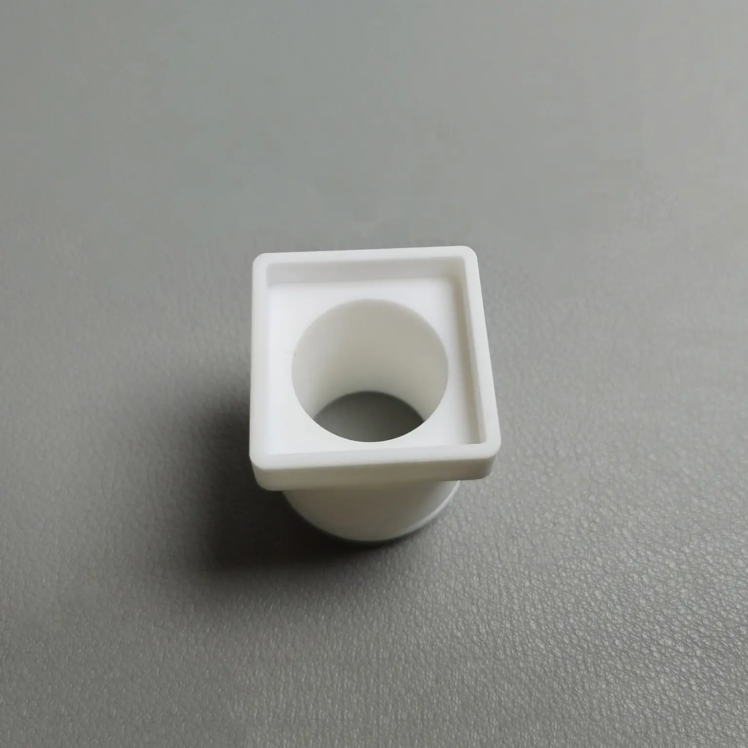
Features may be planned before final firing when geometry, tolerances, or surface access make that appropriate. Identify critical holes, recesses, and mating dimensions early to support a clearer ceramic feedthrough inquiry.
Final Machining
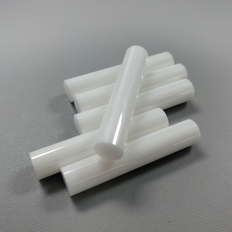
Post-fired machining considerations focus on dimensions, flatness, holes, and surfaces that interface with adjacent hardware. Mark functional surfaces and inspection points on the drawing to distinguish essential requirements from general preferences.

Surface Metallization
Metallized areas may be relevant where a ceramic component must connect with conductive or joined elements. Define the intended interface, coverage area, mating materials, and operating conditions for project-specific review.
Ceramic Metal Joining
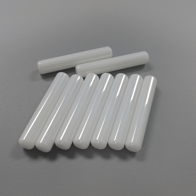
Joining concepts depend on the ceramic grade, metal interface, geometry, and service environment. Provide conductor details, housing information, temperature, pressure or vacuum conditions, and acceptance expectations for a focused discussion.
Associated Hardware for Ceramic Feedthrough Components
Conductive Pins
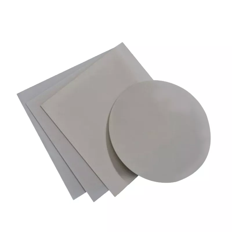
Specify pin material, diameter, projection, quantity, and connection ends for ceramic feedthrough components. Identify signal, power, or sensing duties and the surfaces that must align with the mating assembly.
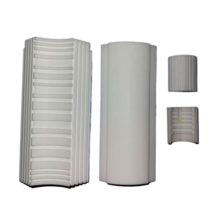
Metal Housings
Describe the housing material, wall interface, envelope dimensions, and attachment method. A drawing should show where the ceramic insulator meets the housing and which features govern installation.

Mounting Flanges
Define flange profile, mounting pattern, sealing face, and available installation space. Include the chamber or equipment interface in the inquiry when flange geometry determines the fit of the finished assembly.
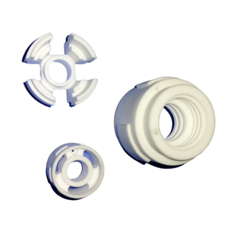
Seal Interfaces
Clarify the intended seal location, mating materials, operating environment, and acceptance expectation. These details help distinguish a ceramic component requirement from the additional joining or assembly questions that need review.
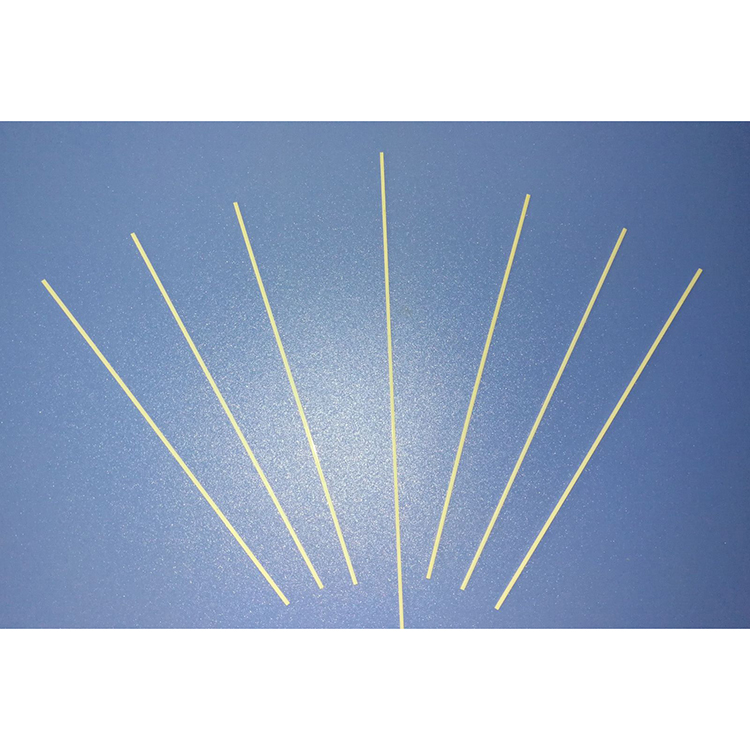
Mating Connectors
Share connector type, pin arrangement, clearance limits, and cable or terminal interface requirements. Reference dimensions and assembly-critical surfaces help Porcecore discuss ceramic feedthrough components against the actual equipment connection.
About Porcecore
Founded by Andy Yuan, Porcecore is a B2B technical ceramics brand for industrial buyers, equipment builders, project teams and distributors. Our mission is straightforward: connect the material choice to a clearly defined part requirement, so sourcing discussions begin with the information that matters.
Our scope includes oxide, nitride, carbide and specialty ceramic families, considered alongside familiar component forms and the demands of the application. For ceramic feedthrough components, we look beyond a material name to geometry, mating surfaces, operating conditions and the inspection expectations that affect the project.
Porcecore works drawing-led and application-first. Send the current drawing revision, known material designation, quantity, service conditions and acceptance criteria; identify assembly-critical surfaces and documentation needs. We help clarify open questions before commitment, giving quotation conversations a more concrete basis.

Ceramic Feedthrough Components: Requirements That Matter
Define Geometry First
Start with the component envelope, conductor count, wall thickness, mounting arrangement, and dimensions that govern assembly. A current drawing revision helps identify what is fixed, what may be adjusted, and which geometry questions need resolution before a quotation discussion.
- Provide the current drawing revision
- Identify critical dimensions and tolerances
- Note single-pin or multi-pin requirements
- Flag features that affect installation

Map the Service Environment
Ceramic feedthrough components should be discussed in the context of their operating environment, not only by material name. Share the relevant temperature, pressure or vacuum conditions, electrical duty, surrounding media, and expected service exposure so the requirement can be reviewed as a whole.
- Describe operating temperature conditions
- State pressure or vacuum expectations
- Clarify electrical duty and interfaces
- Identify exposure to media or chemicals

Identify Mating Surfaces
Interfaces often determine whether a ceramic component works as intended in the final assembly. Call out the surfaces that mate with housings, conductors, seals, or adjacent hardware, along with fit expectations, joining considerations, and assembly constraints that influence the part definition.
- Mark surfaces that locate or seal
- Describe mating materials and hardware
- Specify fit-critical dimensions
- Note joining or mounting constraints

Set Acceptance Criteria
Clear acceptance criteria give a sourcing conversation a practical basis. Define the material designation if known, inspection points, required documentation, quantity, and any project-specific approval expectations. Porcecore can then help distinguish essential requirements from items that remain open for discussion.
- State material grade if known
- List inspection and documentation needs
- Provide quantity and delivery context
- Separate mandatory requirements from preferences
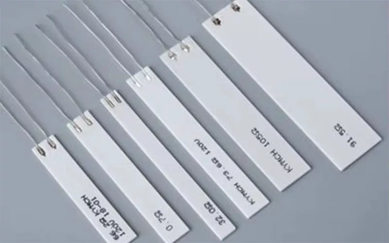
Ceramic Feedthrough Components: A Drawing-Led Conversation
Compare requirement-focused inquiry with material-name-only sourcing before requesting a quotation.
← Swipe left or right to view →
Ceramic Feedthrough Components: From Requirement Review to Next Step
Move from a current drawing and service conditions to a focused quotation discussion with project-specific details confirmed before commitment.
Share Current Part Details
Send the current drawing revision, known material designation, quantity, and the ceramic feedthrough component’s intended operating environment.
Clarify Critical Requirements
Identify assembly-driving dimensions, mating surfaces, electrical interfaces, service conditions, and acceptance criteria that require discussion before a quotation.
Review Material And Geometry
Consider suitable ceramic families, component geometry, and joining or interface considerations against the defined application requirements and open questions.
Discuss Quotation Basis
Use the clarified requirement to discuss scope, documentation needs, delivery expectations, and commercial details for the individual project.
Confirm Project Details
Confirm the agreed drawing, grade, dimensions, tolerances, inspection expectations, and order terms before moving forward with a production decision.
Work With Porcecore on Ceramic Feedthrough Components
Give the quotation discussion a clear engineering basis from the first message.
Send Your Drawing
Email the current drawing revision, replacement-part details, or application description so the component geometry and assembly context can be reviewed.
Define Known Requirements
Identify the material designation, quantity, operating conditions, mating surfaces, and dimensions that matter to the ceramic feedthrough components in your assembly.
Clarify Acceptance Needs
State tolerances, inspection expectations, documentation needs, and any approval criteria that should guide the project-specific quotation conversation.
Review the Next Decision
Porcecore will use the shared requirements to identify open questions and establish a practical basis for the next quotation discussion.
Ceramic Feedthrough Components Documentation Requirements

Evidence and Reference Policy
Customer outcomes and project cases are published only when written approval and supporting evidence are available. For current sourcing decisions, review the controlled drawing, material basis, inspection scope, and project-specific acceptance criteria.
Buyer’s Guide to Ceramic Feedthrough Components
Clarify the drawing, material, inspection, and commercial inputs before requesting a project-specific quotation.
What information should I send for ceramic feedthrough components?
Can Porcecore help select a grade for ceramic feedthrough components?
Which tolerances matter most on ceramic feedthrough components?
Can I request a quotation from a sample or replacement part?
How should service conditions be described for a feedthrough inquiry?
What quantity and packaging details should be included?
What inspection evidence can be discussed before ordering ceramic feedthrough components?
How does Porcecore handle IP-sensitive ceramic feedthrough components inquiries?
Complete Buyer’s Guide to ceramic feedthrough components
Use a practical decision framework to define electrical, thermal, vacuum, and mechanical requirements, compare supplier qualifications, and avoid specification, testing, and sourcing mistakes that can compromise reliability or lead time.
1. What Are Ceramic Feedthrough Components?
Three functions define ceramic feedthrough components: they electrically isolate conductors, separate the enclosure environment, and mechanically locate the conductors as they cross a wall or housing.
Two construction levels must not be confused. A simple ceramic insulator supports and separates a conductor, while a ceramic-to-metal assembly adds a sealed ceramic, conductor, and metal boundary; a feedthrough filter also adds capacitive filtering for unwanted high-frequency energy. Buyers should first state voltage and current, conductor count, temperature, pressure or vacuum conditions, mounting interface, space envelope, and whether leak tightness or filtering is required.
2. Evolution of Ceramic Feedthrough Technology
1900s-era ceramic insulators established the basic model: electrically isolate a conductor while supporting it mechanically. Later equipment required the barrier itself to remain sealed, shifting attention from the ceramic alone to the ceramic-metal interface.
2 process advances made that shift practical: metallization creates a brazeable ceramic surface, while matched expansion and controlled brazing help manage thermal stress. These methods enabled engineered single-pin and multi-pin headers rather than simple standalone insulators. https://www.morgantechnicalceramics.com/en-gb/products/ceramic-to-metal-assemblies/feedthroughs
100 kV-class, RF, and vacuum designs added new procurement requirements: conductor layout, corona control, flange interface, leak testing, and documentation must be specified together. Published industry examples show helium leak testing and configurations for high voltage, RF, and multi-conductor assemblies. https://www.ceramtec-industrial.com/en/products-applications/hermetically-sealed-components/ceramaseal-feedthroughs
3. Types of Ceramic Feedthrough Components
Ceramic feedthrough components are grouped by conductor count, electrical duty, and boundary condition. Configuration sets the insulation path, heat-removal need, sealing approach, and drawing information required for a meaningful quotation.
Single-Pin Feedthroughs

One isolated conductor suits sensors, thermocouples, and simple power leads. Priorities are pin size, mounting envelope, and clearance to the housing.
Multi-Pin Headers

Multiple insulated pins carry signals through one housing opening. Pin count, pitch, cross-talk risk, and serviceability trade against package size.
High-Voltage Designs

High-voltage conductors require controlled creepage, clearance, and field geometry. Voltage type, altitude, contamination, and corona margin must be stated.
High-Current Designs

High-current paths use larger conductors and low-resistance joints. Current profile, temperature rise, cooling, and terminal interfaces drive the design.
RF And Coaxial Feedthroughs

Coaxial designs place a center conductor within a controlled return path. Frequency range, impedance target, connector interface, and power level require review.
Vacuum Or Pressure-Rated Designs

Sealed designs pass conductors through a chamber wall. Vacuum level or pressure, leak-test criterion, media, thermal cycling, and flange details are essential.
4. Materials for Ceramic Feedthrough Components
Alumina is the usual starting point for insulating ceramic feedthrough components, but the seal is a material system. Electrical duty, thermal mismatch, environment, and joining route must be reviewed together.
| Material Family | Typical Role | Review Point |
|---|---|---|
| Alumina | Insulator | Dielectric behavior, grade |
| Aluminum nitride | Insulator | Thermal path, joining |
| Kovar or steel | Housing | Expansion, corrosion |
| Copper or nickel | Conductor | Current, braze compatibility |
| Silver-copper braze | Seal joint | Cycle and cleanliness |
Insulator Families
Alumina prioritizes dielectric insulation and a proven ceramic-to-metal route. Aluminum nitride or silicon nitride may suit heat-transfer or mechanical requirements, subject to grade-specific data.
Metal And Braze Pairing
Kovar, stainless steel, nickel, copper, and nickel-iron alloys are housing or conductor candidates. Match thermal expansion across ceramic, metallization, braze, and housing through the full temperature cycle.
RFQ Material Data
RFQs should state ceramic grade, conductor and housing alloys, braze family, and metallization method. Add voltage or RF duty, corrosion exposure, vacuum-cleanliness expectations, temperature range, cycling, and acceptance documentation.
5. Configurations and Custom Design Options
Ceramic feedthrough components are customized around the barrier, conductors and installation envelope. Configuration choices require engineering validation because each change can affect insulation, sealing, heat flow and assembly.
| Customization Area | Required Input | Validation Focus |
|---|---|---|
| Conductors | Pin map and ratings | Spacing and insulation |
| Mounting | Drawing and mating part | Fit and joining |
| Environment | Temperature, media, pressure | Seal and cooling |
Electrical Layout
Pin count, pitch, conductor diameter and coaxial or blade geometry should be fixed against voltage, current, frequency and clearance requirements.
Mechanical Interfaces

Flange pattern, weld land, threaded fitting, connector termination and housing alloy require a current drawing plus mating-part dimensions and datum scheme.
Service Conditions
Seal approach, shielding and cooling provisions depend on vacuum or pressure level, temperature range, media, thermal cycling and electromagnetic environment.
6. Critical Construction and Quality Elements
A current drawing revision should show the ceramic profile, metal interfaces, and duty-cycle limits. The buyer’s question is whether design and inspection evidence supports the intended service.
Ceramic And Metal Seal
Ceramic geometry must avoid stress concentrators at bores, shoulders, and brazed edges. Metallization coverage and braze-joint continuity should match the specified joining surfaces.
Compatible thermal expansion between ceramic, conductor, and housing reduces cycling stress; confirm the selected material combination.
Electrical Geometry
Creepage and clearance dimensions require review against voltage, contamination, pressure, and surrounding medium. Corona-control contours are relevant where electric-field concentration could initiate discharge.
Conductor alignment must preserve pin spacing and prevent assembly-side loading.
Inspection And Mounting
Inspection evidence should identify the agreed leak, electrical, dimensional, and joint-verification methods. Acceptance criteria belong on the drawing or purchase specification.
Mounting interfaces—flange, weld land, braze feature, or threaded fitting—must define sealing faces, loads, and installation sequence.
7. How to Select a Feedthrough Manufacturer
Selection should begin with the operating envelope and controlled drawing, not a catalog image. Compare suppliers against identical requirements, evidence packages, prototype routes, and dated delivery assumptions.
| Area | Request | Clarify |
|---|---|---|
| Engineering | Design review | Joining risks |
| Quality | Inspection plan | Lot records |
| Delivery | Capacity plan | Lead-time assumptions |
Engineering And Joining
Ask who reviews interfaces, material grade, metallization, and braze or seal design. Require written closure of open risks before quotation.
Quality Evidence
Request tolerance methods, inspection plans, traceability scope, and applicable test capability. Confirm which records accompany each lot rather than assuming shared certifications.
RFQ Comparison Checklist
One RFQ package makes technical and commercial comparisons fair.
- Current drawing revision and critical interfaces
- Service conditions and acceptance criteria
- Prototype quantity and production forecast
- Required reports, samples, and delivery date
8. Common Ceramic Feedthrough Components Buying Mistakes
Seven recurring specification gaps turn a seemingly suitable feedthrough into an assembly, reliability, or commercial mismatch. Resolve them before drawing release, not after samples arrive.
Electrical Duty Is Incomplete
Voltage alone omits altitude, contamination, pressure, current, and frequency; overheating, tracking, or unstable RF behavior can follow. Ask: What are the full electrical and environmental duty conditions?
Seal And Interface Assumptions
Thermal-expansion mismatch, undefined hermetic testing, and unreviewed mating faces can compromise seals or prevent installation. Ask: What leak test, temperature cycle, flange, pin, and connector interfaces govern acceptance?
Density And Quote Scope
Selecting pin density before clearance and routing review can force redesign. Comparing quotes without equivalent drawings, materials, tests, documentation, and delivery terms obscures value. Ask: Which requirements are included in every quotation?
9. From Requirements to Production Release
A production release should turn service demands into controlled, checkable requirements. For ceramic feedthrough components, each gate needs a named owner and a recorded decision.
Capture Service Conditions
First, engineering defines voltage, current, temperature, pressure or vacuum, media, cycling, and installation constraints. Procurement records forecast quantity and target delivery.
Review And Validate Prototypes
Then, supplier and engineering review manufacturability and prototype the agreed configuration. Quality approves test methods, samples, and results before design freeze.
Release And Inspect Production
Finally, quality agrees acceptance criteria and required documentation; procurement issues the controlled order. Incoming inspection verifies the delivered lot against the approved drawing, records, and purchase requirements.
10. Ceramic Feedthrough Components Pricing and Lead Time
1 comparable quotation starts with the current drawing revision, quantity tier, pin count, service conditions, acceptance criteria, and required documentation. Unit pricing is quote-based because geometry, material grade, housing choice, and inspection scope change the work content.
2 schedule stages usually matter more than a headline lead-time promise: design review, tooling where needed, sampling, qualification, and production release can each add time. State whether first articles, leak testing, electrical testing, certificates, or traceability records are required before comparing offers.
| Cost and lead-time driver | Typical quotation effect |
|---|---|
| Low quantity or new design | Higher unit cost; development steps may extend lead time |
| More pins or complex housing | More assembly and inspection effort |
| Tooling or qualification testing | Upfront cost and added release time |
| Production quantity with stable documentation | Lower unit-cost potential; more predictable scheduling |
Discuss Your Ceramic Feedthrough Components Requirement
Email your drawing, service conditions, and acceptance criteria to start a clearer project conversation with Porcecore.